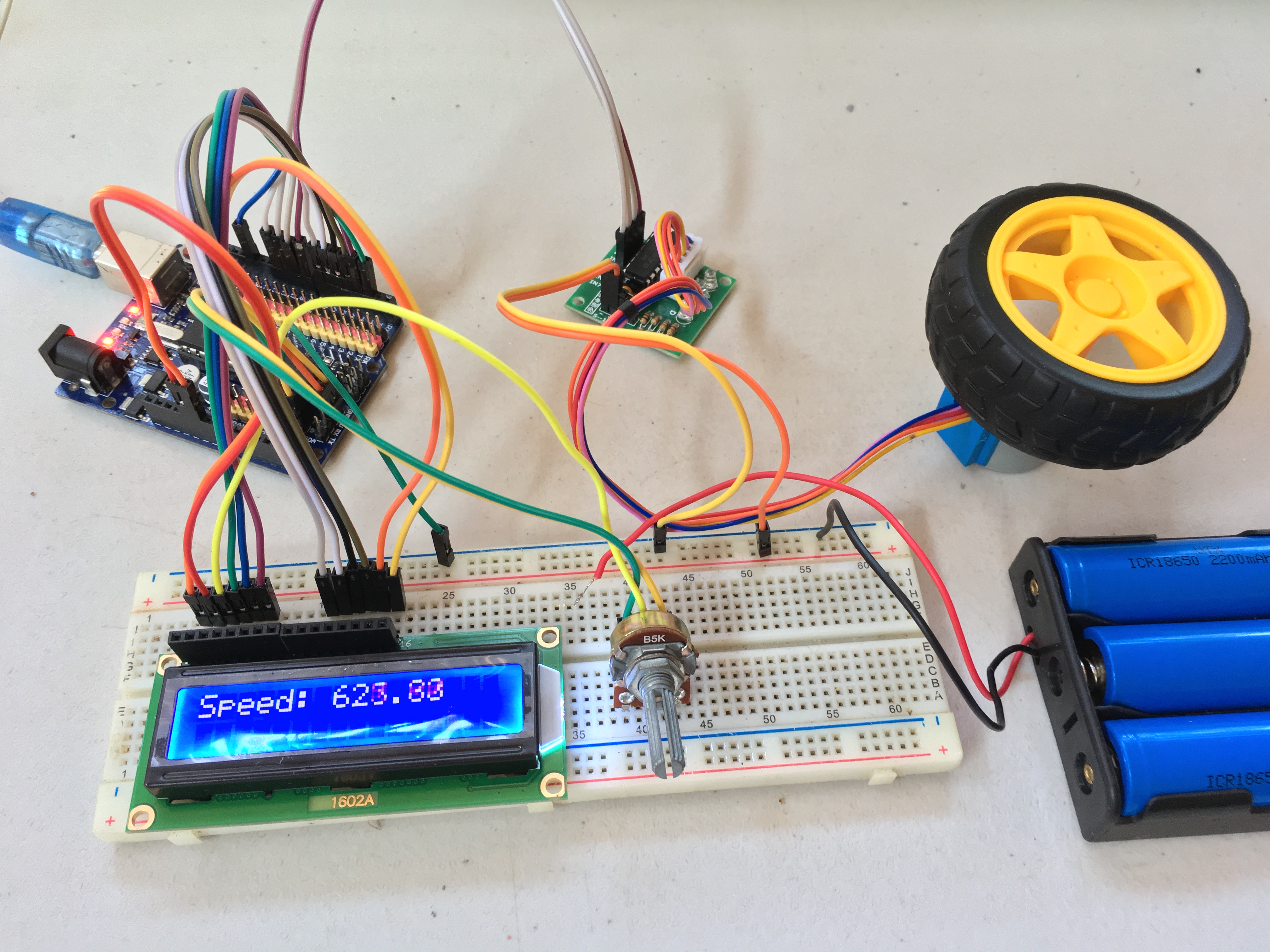
Thus we develop a arduino based stepper motor controller system that allows the user to control a stepper motor motion in 3 different modes.
#Stepper motor arduino driver#
Also it uses a stepper driver to rotate the motor step by step respectively as per manual rotation of optical encoder. When user rotates the knob the rotation steps are transmitted to the controller and the arduino displays no of steps on an LCD display. The TB6600 stepper motor driver is used to control larger two-phase bipolar stepper motors like NEMA 23 motors used in 3D printers, CNC machines and robots. The optical encoder is fitted with a knob to help rotate it. When switched in this mode the user can control motor movement using an optical encoder.
#Stepper motor arduino full#
This mode gives a full manual control of the stepper motor to the user. Pressing the same button again the motor rotates another quarter starting from the last point at which t stopped. On a button press the stepper motor rotates exactly one quarter rotation and stops. When switched in this mode the user can press a red button. It can be controlled with high accuracy due to its design. Download the easy-to-use Arduino software library, check out the examples.

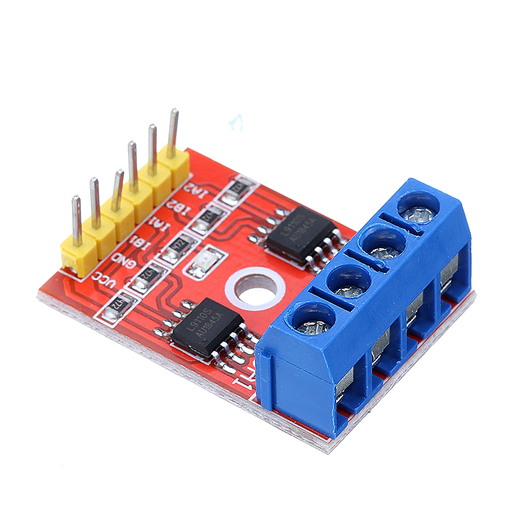
5.00 out of 5 2 customer reviewsAdd a review 2.20. In this mode the stepper motor movement is restricted to quarter of a rotation. The stepper motor does not require any feedback for its operation. L293D Arduino Motor Shield Motor Stepper Driver, 2x L9110. The motor can now be rotated continuously in clockwise as well as anti clockwise direction using a simple switch button. Switching the system in full rotation mode allows user to control the motor direction without stopping. The system makes use of Arduino uno controller along with an LCD Display, NEMA Stepper motor, optical encoder, stepper driver, switches and buttons along with basic electronics component and PCB to develop this system. We here develop an arduino based stepper motor controller that allows user to control the stepper in 3 different modes: Each pulse rotates the shaft through a fixed angle. The stepper motor is known for its property of converting a train of input pulses (typically square waves) into a precisely defined increment in the shaft’s rotational position. Well use the Arduino built-in Stepper.h library. That’s because they divide one full shaft rotation in to a number of equal steps. There are different ways to control stepper motors with a microcontroller. Actually DRV8825 is conveniently laid out to match the 4-pin connector on several bipolar motors so, that shouldn’t be a problem. Connect the stepper motor to the B2, B1, A1 & A2 pins. Connect the DIR and STEP input pins to the 2 and 3 digital output pins on the Arduino. Stepper motors are also known as step motor or stepping motors. Connect GND LOGIC pin to the ground pin on the Arduino.


 0 kommentar(er)
